National hotline:+86 18809263088
Leave Your Message
0%

Picking an Oil-Immersed Transformer isn't just about matching voltage ratings, you know? It’s actually more nuanced than that. The right one depends on a bunch of factors like your load needs, where you're installing it, how you plan to cool it down, and even what your future growth looks like. For example, a unit right next to a factory line will face totally different demands compared to one tucked away inside a quiet office building. Little things really can make a difference—things like the ambient temperature, space availability, how easy it is to do maintenance, and how much your load could change down the line.

In this guide, I’ve put together seven practical tips—from making sure The Transformer can handle your load and checking insulation needs, to examining cooling options, protection measures, and how accessible it is for service. Martin J. Heathcote, who wrote *The J & P Transformer Book*, is considered a real authority in transformer engineering. To paraphrase his advice—because I think it’s worth sharing—it's all about choosing equipment based on how you'll actually use it, not just what the nameplate says. That little shift in thinking can save you from ending up with something totally unsuited, which could cost a lot later on. But honestly, even the best checklist can’t replace a site-specific engineering review. Sometimes, even a carefully picked transformer can let you down if you’ve misunderstood the environment it’s operating in.

The tips I’m sharing focus on things you can actually verify—like the rated power, voltage, how much it heats up, what kind of enclosure it needs, and maintenance considerations. Be sure to ask your suppliers for clear technical data and run your assumptions by a qualified engineer. Don’t just think about the purchase price—things like oil quality, installation costs, inspections, and ongoing operating conditions are just as important when deciding what’s best for you. And it’s totally normal not to have all the answers upfront—some project details will be uncertain, and that’s okay. It’s better to acknowledge that early rather than pretend everything has a perfect solution.
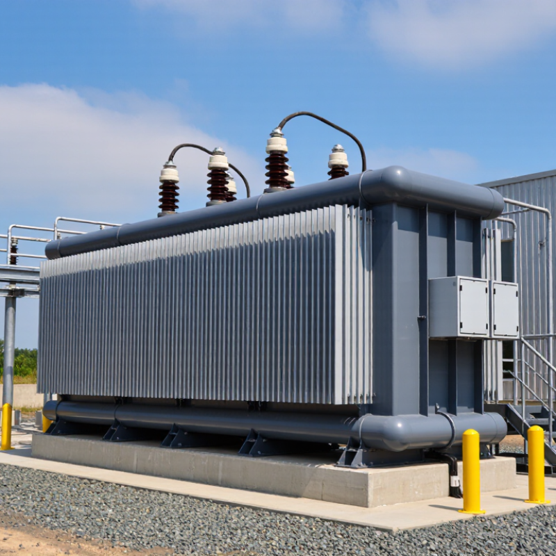
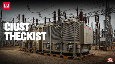
7 Tips for Choosing an Oil Immersed Transformer?

Specify kVA, voltage, and 50/60 Hz frequency under IEC 60076-1

When specifying an Oil Immersed Type Transformer, define the required kVA, voltage, and frequency together. IEC 60076-1 covers transformer ratings and general requirements; the nameplate should match the actual supply, not just a catalog value. State the primary and secondary voltages, system frequency, and expected loading. Include likely overloads, motor starts, or future capacity where relevant. Small omissions matter.

Frequency affects magnetic flux. A transformer’s voltage-to-frequency ratio must stay within its design limits, so never assume a 50 Hz unit suits a 60 Hz system at the same voltage. Ask the supplier to confirm the permitted voltage-frequency combination and operating temperature rise. Also specify tap range and connection arrangement; these details can change how the transformer fits the network. One awkward gap remains: load forecasts are often less certain than the nameplate suggests.

The scale of grid investment makes careful specification increasingly important. The International Energy Agency’s 2023 report, Electricity Grids and Secure Energy Transitions, says annual grid investment needs to rise above USD 600 billion by 2030, from about USD 300 billion today. That is not a transformer-sizing rule, but it signals growing pressure on equipment planning. Put kVA, voltage, and 50/60 Hz requirements in the inquiry, then verify them against IEC 60076-1 and the site’s measured supply. Check twice.

Match ONAN or ONAF cooling to continuous and peak-load requirements

For an oil-immersed transformer, size ONAN cooling around the load it must carry continuously. ONAN relies on natural oil and air circulation, so it avoids fan power and fan-related maintenance. Check the actual site conditions, not just the catalogue rating: ambient temperature, enclosure airflow, altitude, and harmonic loads all affect thermal performance. IEC 60076-2:2011 gives 60 K as the top-liquid temperature-rise limit and 65 K for average winding rise under specified conditions. These are design limits, not a promise that every installation will run at its full rating. Small details matter.

Use ONAF when peaks are significant but intermittent, and confirm the transformer’s fan-cooled rating covers their duration. Fans increase heat removal, but they do not make every peak harmless. IEEE C57.91-2011 treats 110°C as a reference winding hot-spot temperature for loading and insulation-aging calculations; sustained higher temperatures can shorten insulation life. Ask for ONAN and ONAF ratings, fan-failure limits, and the permitted loading profile. Then compare those values with measured demand, including how often peaks occur and how long they last. A practical check: verify that cooling alarms and fan controls are tested. I would be cautious about selecting ONAF solely for a brief worst-case spike; real load patterns are often messier than forecasts.

Compare temperature-rise limits: 60 K top oil and 65 K winding per IEC 60076-2

When comparing oil-immersed transformers, check temperature rise against the applicable edition of IEC 60076-2. Common reference limits are 60 K for top oil and 65 K for average winding rise. These are rises above ambient, not final operating temperatures. Small details matter.

Ask how the figures were measured and under which cooling mode. A test report should identify the ambient conditions, rated load, and measurement method. Compare like with like: a transformer tested with forced cooling may not behave the same way under natural cooling. Look closely. A passing result alone does not show how much thermal margin remains during demanding service.

Temperature rise affects insulation aging and expected service life, but it is only one selection factor. Check the proposed loading pattern, site climate, enclosure ventilation, and likely overload duration with a qualified engineer. Confirm that the specified limits match the transformer’s design and contract requirements; standards and project specifications may differ. I would not treat 60 K and 65 K as a complete guarantee. Even a compliant unit can run hotter than expected if actual conditions differ from the test assumptions. That is easy to overlook.

Verify insulating mineral oil quality against IEC 60296 requirements

An oil-immersed transformer depends on insulating oil that can withstand electrical stress and carry heat away from the windings. Ask for a test certificate showing that the unused mineral oil meets the relevant IEC 60296 requirements. Check that the certificate names the oil category, applicable edition, test methods, and batch number.

Looks can mislead. Clear oil in a sample bottle does not prove low moisture or adequate dielectric strength.

Review the reported breakdown voltage, water content, acidity, and interfacial tension against the specified limits. Confirm oxidation stability and inhibitor content where they apply to the selected oil type.

Check that the delivery documents and container markings match the tested batch. Check the batch. Take samples with clean, dry equipment; a damp sampling bottle can distort results.

For critical installations, consider independent laboratory testing before filling, since a supplier certificate cannot show how oil was stored or handled afterward. It is easy to focus on one attractive test result and overlook the rest. Compare the full report, and ask for clarification when units, methods, or results are missing.

Check short-circuit withstand capability under IEC 60076-5

Short-circuit withstand capability is not a catalogue checkbox. It determines whether windings, leads, and clamping structures can survive the forces produced by a fault. IEC 60076-5:2006 uses a two-second reference duration for thermal short-circuit calculations, unless another duration is agreed. The standard also requires attention to dynamic effects, which depend on the prospective current and the transformer’s impedance. Check that the supplier’s calculations match the specified system fault level, not just the transformer’s rated power.

Ask for documented evidence: short-circuit calculations, winding mechanical design details, and test records where available. A Transformer Oil Immersed Type unit may have robust insulation, yet oil does not prevent winding movement under high electromagnetic forces. Look closely at conductor support and clamping details. Small omissions matter. CIGRE Technical Brochure 642, a transformer reliability survey, provides industry context for assessing failure risks, but it cannot replace unit-specific verification. One point worth questioning: a compliant calculation is only as useful as its assumptions. Confirm source impedance, X/R ratio, and protection clearing time with the system designer before approval.

Short-Circuit Withstand: Impedance and Prospective Current

Lower transformer impedance results in higher prospective short-circuit current. The values shown are idealized estimates for a stiff source, calculated as 100 divided by transformer impedance in percent: 25, 16.7, 12.5, and 10 per unit, respectively. They are not withstand ratings or pass/fail limits. Check the actual system fault level, transformer design, and thermal and mechanical withstand assessment against IEC 60076-5.

Assess loading and thermal aging using the IEC 60076-7 loading guide

Oil-immersed transformer loading is a heat problem, not merely a nameplate calculation. IEC 60076-7:2018 estimates top-oil and winding hot-spot temperatures from load, ambient temperature, and cooling conditions. For a single phase oil-immersed transformer, record actual load cycles and nearby air temperatures. An 80% load in a hot equipment room can age insulation differently from the same load outdoors. Heat hides in peaks.

For conventional paper insulation, IEC 60076-7 uses a reference hot-spot temperature of 98°C, with ageing roughly doubling for every 6°C rise. Its model therefore gives about four times the reference ageing rate at 110°C. Thermally upgraded paper follows a different equation, so that figure cannot be applied blindly. IEEE C57.91-2011 also evaluates hottest-spot temperature and cumulative insulation ageing when assessing loading.

Check cooling fans, radiator surfaces, and oil circulation during peak demand; dust or a failed fan can change the thermal picture. Compare calculated temperatures with sensor readings where available, then assess how long the transformer remains near peak load. I would not treat one neat spreadsheet as proof: sensor placement and changing ambient conditions can distort the estimate. That deserves a second look.

7 Tips for Choosing an Oil Immersed Transformer? - Assess loading and thermal aging using the IEC 60076-7 loading guide

Use the following checklist to compare transformer options and assess operating conditions. Record actual site and manufacturer data; loading capability and insulation aging depend on the transformer design and operating conditions.

Tip What to assess Data to collect How to use the IEC 60076-7 loading guide Selection or operating decision
1. Define the load profile Identify normal, peak, emergency, and seasonal demand rather than relying on a single maximum-load figure. Load in kVA or MVA; percentage of rated power; time interval; duration and frequency of peaks; load power factor; expected load growth. Evaluate the time-varying load sequence together with the transformer’s thermal response. A short peak and a sustained load can have different thermal effects. Choose a rating that accommodates the expected profile without assuming that temporary overload capability is continuous capacity.
2. Confirm site ambient conditions Account for the ambient temperature around the transformer and its variation over time. Ambient temperature in °C; measurement location; hourly or daily profile; seasonal extremes; indoor or outdoor installation; ventilation conditions. Use ambient temperature as an input to the thermal assessment. Higher ambient temperature reduces the temperature margin available for a given load. Check the proposed transformer and cooling arrangement against the actual installation environment and applicable specifications.
3. Check cooling equipment and mode Verify the cooling method, available cooling stages, and the condition of fans, pumps, radiators, and controls where fitted. Cooling designation and operating mode; fan and pump status; alarm or trip records; maintenance history; control settings; radiator condition. Model or assess loading using the cooling mode that is actually available. Do not assume forced cooling is operating if equipment is unavailable or switched off. Confirm that the transformer’s cooling equipment and monitoring are suitable for the intended duty and maintenance capability.
4. Estimate winding hot-spot temperature Assess the winding hot spot, which is important for insulation thermal aging and may not be represented by top-oil temperature alone. Top-oil temperature in °C; winding hot-spot estimate or measurement in °C; load history; ambient temperature; transformer thermal data; sensor and model details. Apply the guide’s thermal model and the transformer-specific data needed to estimate hot-spot temperature over the load cycle. Prefer a design and monitoring approach that provides reliable temperature assessment for the expected loading conditions.
5. Assess insulation aging Consider cumulative thermal aging as well as the temperature reached during an individual loading event. Hot-spot temperature history; duration at each loading level; insulation paper type, if known; prior loading and operating records. Use the guide’s relative aging and loss-of-life methodology, with the appropriate insulation assumptions. Treat calculated aging as an estimate, not a direct measurement of remaining life. Compare loading scenarios over the relevant operating period and avoid basing a decision on a single temperature reading.
6. Review transformer-specific limits Check that the proposed loading assessment reflects the individual transformer’s design, condition, and stated operating limits. Rated power and voltage; nameplate data; impedance; temperature-rise information; cooling details; manufacturer loading guidance; condition and maintenance findings. Use transformer-specific parameters wherever required by the guide. Generic assumptions cannot establish a universal permissible overload or loading duration. Obtain a qualified engineering review when key thermal data are unavailable or when the proposed duty is outside normal service conditions.
7. Plan monitoring and contingencies Ensure operating staff can detect abnormal temperatures, cooling failures, and changing load conditions. Load and temperature alarms; sensor availability; cooling-system alarms; inspection schedule; event logs; contingency and maintenance procedures. Use monitored operating data to validate assumptions and reassess loading and aging when ambient conditions, cooling performance, or the load profile changes. Select a transformer and monitoring arrangement that support safe operation, timely maintenance, and documented review of loading events.

Important: IEC 60076-7 provides guidance for evaluating loading and thermal effects; it does not establish one overload limit that applies to every transformer. Confirm the applicable edition, transformer design data, insulation assumptions, condition, and site requirements before making operating or procurement decisions.

Plan oil sampling and dissolved-gas analysis according to IEC 60599

When choosing an Oil-Immersed Power Transformer, plan condition monitoring before commissioning. Dissolved-gas analysis (DGA) can indicate developing thermal or electrical faults, but one sample rarely tells the whole story. IEC 60599 provides guidance for interpreting gas concentrations and trends in mineral-oil equipment. It does not replace careful sampling. Follow a suitable sampling and gas-analysis procedure, such as IEC 60567 where applicable.

Tip: Record a baseline sample, then set repeat intervals according to transformer age, loading, criticality, and operating history. Use the same sampling point and method each time. Note the load, oil temperature, and recent operating events on the sample record. Small details matter.

Collect oil in clean, gas-tight equipment, avoiding air bubbles and unnecessary exposure. Label each sample clearly and send it promptly to a qualified laboratory. Compare results with earlier readings, not just generic limits. A rising gas level may deserve attention even when it remains below an alarm threshold. Ratios can help, but they are not a diagnosis on their own. Field notes are sometimes incomplete; that is a weakness worth correcting before the next sample.

How Efficient Power Smart Dry Transformers Strengthen Modern Energy Systems

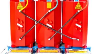
Modern energy systems need distribution equipment that can reduce losses while responding intelligently to changing loads. The U.S. Department of Energy’s 2024 distribution-transformer efficiency rule estimates that its standards will save 10.9 quadrillion Btu over 30 years across covered transformers. Though this estimate applies to the regulated transformer market as a whole—not to dry-type units alone—it highlights the system-wide value of efficiency. High-efficiency dry-type transformers can support that goal through reduced conversion losses, while avoiding the use of insulating oil.

Intelligent monitoring adds operational value. Sensors that track temperature, load and equipment condition can help operators identify developing problems, balance demand and plan maintenance before faults interrupt service. These capabilities matter as grids accommodate more renewable generation and electrified loads. The International Energy Agency’s *Electricity Grids and Secure Energy Transitions* report says annual grid investment needs to rise to more than $600 billion by 2030 to meet global energy goals. Combining efficient power conversion with real-time operating data can help make each network investment work harder, improving reliability and energy management at the distribution level.

FAQS

What do 60 K and 65 K temperature-rise limits mean?

They are rises above ambient, not final temperatures. Common reference limits are 60 K for top oil and 65 K for average winding rise. Small distinction, big difference.

What should a transformer temperature-rise test report include?

Check ambient conditions, rated load, measurement method, and cooling mode. Compare results under similar conditions. Forced cooling can produce different results from natural cooling.

Does passing a temperature-rise test guarantee enough thermal margin?

No. A passing result does not show how much margin remains during demanding service. Site climate, ventilation, loading, and overload duration matter too.

How can I check the quality of unused insulating mineral oil?

Review a test certificate against the applicable IEC 60296 requirements. It should identify the oil category, edition, test methods, and batch number. Clear oil proves little.

Which oil test results deserve attention?

Compare breakdown voltage, water content, acidity, and interfacial tension with specified limits. Check oxidation stability and inhibitor content when relevant. Read the full report.

Why do oil samples need careful handling?

Use clean, dry sampling equipment. A damp bottle can distort moisture results. Match container markings and delivery documents to the tested batch. Easy to miss.

How does loading affect insulation aging?

The IEC 60076-7:2018 guide estimates hot-spot and top-oil temperatures using load, ambient temperature, and cooling conditions. An 80% load in a hot room may age insulation faster than the same load outdoors.

Can the 98°C reference temperature apply to every transformer?

No. For conventional paper insulation, the guide uses 98°C as a reference; ageing roughly doubles per 6°C rise. Thermally upgraded paper follows a different equation, so check the insulation type.

What should I check during peak demand?

Inspect fans, radiator surfaces, and oil circulation. Compare calculated temperatures with sensor readings, while considering sensor placement and changing ambient conditions. One spreadsheet is not proof.

Conclusion

Choosing an Oil Immersed Transformer begins with matching its rated kVA, voltage, and operating frequency to the electrical system, in accordance with IEC 60076-1. Cooling should also suit expected demand: ONAN may be appropriate for steady loads, while ONAF can provide additional capacity during peak periods. Compare specified temperature-rise limits with IEC 60076-2 guidance, including the stated 60 K top-oil and 65 K winding values, and confirm that the insulating mineral oil meets IEC 60296 requirements.

Reliability also depends on the transformer's ability to withstand short-circuit stresses under IEC 60076-5 and on managing loading and thermal aging using the IEC 60076-7 loading guide. Finally, plan routine oil sampling and dissolved-gas analysis in line with IEC 60599. Reviewing these factors together helps ensure the transformer is appropriately specified, monitored, and suited to its expected operating conditions.

Sophie

Sophie

Sophie is a dedicated marketing professional at Golden Triangle Power Technology Co., Ltd., where she leverages her expertise to highlight the company's innovative products and services. With a deep understanding of the power technology sector, Sophie plays a crucial role in crafting informative......
Previous Top 10 Step Up Down Transformer Suppliers Worldwide